Research Article Archive Versions 2 Vol 2 (3) : 19020304 2019
Download
An Innovative Method to Improve Model Accuracy by Implementing Multi-models Scheme for 28nm Node and Below
: 2019 - 08 - 02
: 2019 - 09 - 28
4637 31 0
Abstract & Keywords
Abstract: As the process comes into 28nm node and below, lithography struggles stronger between high resolution (high NA) and enough process window especially for hole layers (Contacts and Vias). Taking more care of process window may result in lower image quality of structures and bigger uncertainty in OPC model accuracy. Besides, it is difficult to cover all kinds of test structures within acceptable accuracy in one OPC model because of distinct difference of image quality of different patterns. To solve these problems, this paper introduces an innovative method of applying multi-models in one layer OPC. According to different characteristic features, multiple models are applied respectively and the fitting on these features with poor resolution can be improved by re-optimizing based on related model. A practice for 28 nm Via layer modeling calibration is given, and it shows an evident improvement of model accuracy through the implementing of multiple models scheme.
Keywords: Image quality; lithography; OPC model; multi-model
1.   Introduction
As circuit components are packed in ever-closer proximity and the feature size becomes smaller than the lithographic wavelength in advanced technology, the distortions of design shapes become a crucial challenge for process manufacturability. Therefore, various intensive Resolution Enhancement Techniques (RETs) are proposed and introduced in most modern manufacturing to guarantee the integrity of feature patterns. Among the available RETs, Optical Proximity Correction (OPC) is the most popularly method used in modern optical-lithography.
In a typical OPC flow, edges of layout polygons are broken into smaller fragments and the latent image on the resist is then calculated using the OPC models. The differences between the desired image and the latent image are calculated at each fragment and tends to reach to the minimum by moving the fragments iteratively. Therefore, the quality of the OPC solution is highly dependent on the accuracy with which the OPC models, including an optical and a resist model predict the latent image on the resist at each fragment.
A common practice in calibrating OPC models is to collect dimension data of some test structures on mask along with the corresponding data on wafer after exposure and then apply them to tune the models for good predictions. Optimization of the optical components consists of finding the best combination of beam focus, apodization loss, image diffusion, etc.in order to minimize the overall RMS between measured and simulation data of test structures. The choice of these parameters will be dependent on the extent of aerial image parameters coverage, i.e. the calibration features should include aerial images parameters that are of primary concern.
There is a strong correlation between the accuracy of a model and the aerial image quality. The features with the larger uncertainty in the model fitness are those with lower image contrast or a combination of lower Imax and lower slope which are in limited resolution. The CDSEM metrology of these features is based on a larger number of sites and involves data filtering, which can be ruled out as a major source of uncertainty. Thus, the uncertainty in model accuracy are correlated to the weak resolution of these features rather than noise in metrology [1].
In model calibration procedure, the optimization of image diffusion is one important link, which is used to convolve the image to compensate for mask distortions or other factors. The image diffusion parameter is optimized by considering all the points in the calibration data set. A variety of the features in the calibration data set have good contrast and therefore the image diffusion used in the model is biased towards features with good contrast. If the image is diffused more on the lower contrast features, the accuracy of the model can be improved at these features but must undergo the compensation of worse fitting of good contrast [2]. So there has to be a balance between good and poor resolution features to prevent any catastrophic failures.
In recent years, as the process comes into 28nm node and below, it becomes more pressing to balance high resolution (high NA) and enough process window especially for hole layers (Contacts and Vias). And it is difficult to cover all kinds of features in one OPC model. Therefore this paper proposes multi-models for various features in same OPC layer. The fitting of these features with poor resolution can be improved by re-optimization and saved as a second OPC model.
2   Model Calibration and Multi-models Calibration Scheme
2.1.   Traditional Single Model Calibration
OPC models are mathematical models of lithography fabrication process, which include an optical model of describing describe the imaging system characteristics in wafer printing process, and a resist model of capturing capture the empirical resist process responses. It requires a large amount of the dimension data of test structures on the mask and measurement data on the wafer after exposure.


Figure 1.   Typical OPC model calibration flow.
The calibration flow is illustrated in Figure1. In this flow, a single calibrated model is involved which needs to be tuned to fit all measurement data. Generally, a layout may contain a large variety of pattern shapes including one-dimensional (1D) and two-dimensional (2D) features, different sizes and pitches, or even phase shifted and binary features. The image property varies significantly across all these different feature types, which makes it difficult to use one single model to cover them all. Sometimes a model can be tuned to fit very well on line edges, but poorly on line ends; or very well on binary edges, but poorly on phase shift edges. Therefore, compromises often need to be made in order to obtain acceptable fitting across all different types. In the next section, we shall elaborate these issues by studying image and model characteristics with simulation data.
2.2.   Multi-models Calibration
Basically there are two methods for implementing multi-model scheme in a decided lithography process. One is to do model calibration first following the typical flow, then analyze model fitting results and divide calibration data into several groups according to the fitting error trend, and setup every model for each group. This will be illustrated in a practice for 28nm Via layer. The other way is first to group the test structures according to optical characteristics (such as Imax, Imin, Contrast etc.), and do model calibration for every group It has been reported that there is a strong correlation between the accuracy of a model and the aerial image quality. Patterns with different structure characteristics may have different image quality so that it is impossible for all patterns to have a good fitting. Both ways above based on multi-models are able to be synthetically employed to get an ideal models combination and solve the problem effectively.
The model calibration flow for multi-models scheme is shown in Figure 2. Measurement data is first divided into different groups according to the fitting results or test pattern structures and then create each group a sample sheet. The sheet used in model calibration is the same as the one used in conventional flow. Then a combination of models is ready to be included in OPC recipe, which is the script of OPC correction procedure. Finally the layout after correction shall be transferred to mask shop for mask processing.


Figure 2.   Multiple models calibration flow in OPC.
3.   A Multi-model Practice for 28nm Via
Via is the back end layer that impacted severely due to wafer topography issue. To ensure a successful manufacture enough process window should be given for overcoming of focus, dose variation in the procedure of exposure. In this case, two kinds of patterns are selected: matrix array and horizontal array with a range of different pitches both in x and y directions. The patterns and the corresponding scattering bars are showed in Figure 3.


Figure 3.   Multiple models calibration flow in OPC. (a) Matrix square array; (b) Matrix square array with scattering bar; (c) Square horizontal array; (d) Square horizontal array with scattering bar.
3.1.   Traditional Single Model Calibration Results
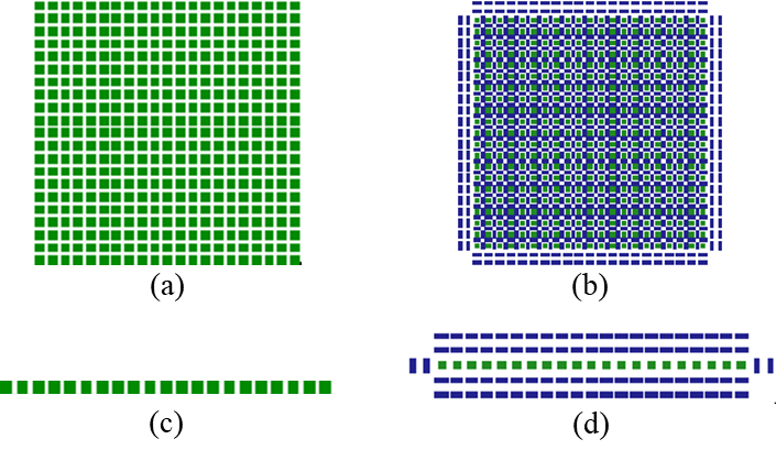
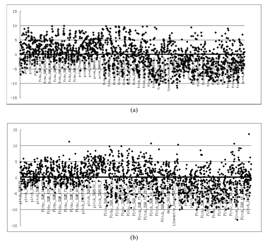
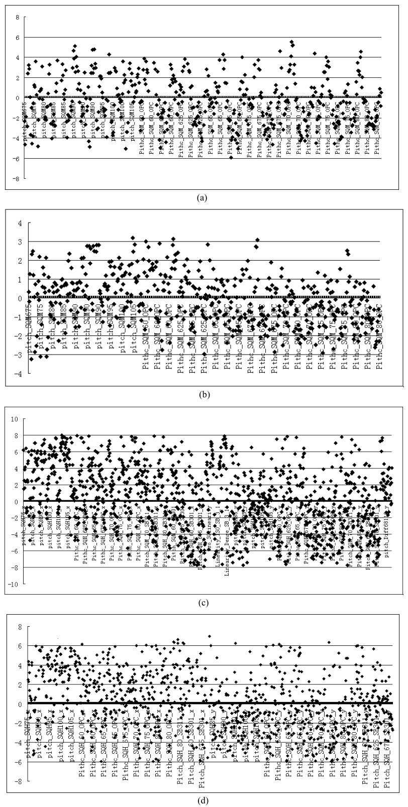
Figure 4 shows the calibration results by single model. After optical model calibration, the best one with an optimum combination of optical parameters is selected out for analyzing and building corresponding resist model. In Figure 4 (a) and (b), it can be seen that the range of difference between simulated and measured CD for most test patterns joined in calibration is from -10nm to 10nm. Obviously, this error range is very big for the model prediction of layout CD performance on wafer in 28nm node. Since there is a notable distinction between matrix and horizontal array of square islands the care of the fitting error of one kind pattern may result of worse fitting of the other kind pattern. Therefore, it is wise to split into two kinds of patterns and build models respectively.


Figure 4.   Single model calibration results (a) optical model fitting results (b) resist model fitting results.
3.2. Multi-model Calibration Results for Matrix and Horizontal Array
During this calibration, the matrix array and horizontal array are divided into two groups, and two models are calibrated respectively base on their group data. The results in Figure 5 shows that the optical mode fitting error range of matrix square array is improved evidently from (-5nm, 8nm) to (-4nm, 4nm), and resist model fitting error range is improved from (-5nm, 5nm) to (-3nm, 3nm). For horizontal patterns the optical model CD fitting error range improved from (-10nm 7nm) to (-8nm, 8nm) and resist model fitting error improved from (-10nm, 5nm) to (-5nm 5nm). Since there exits unsymmetrical optical intensity distribution, which makes image quality worse, the improvement in horizontal array is not as good as that in matrix array.
The optical model parameters of matrix and single model are list contrastively in Table 1. OBJECTIVE, which is defined as overall RMS between weighted simulation and measurement data, indicates the model accuracy. Though small OBJECTIVE does not ensure the model is ideal, OBJECTIVE of matrix model is smaller than single model. Other optical parameters like DEF_START, EDGE_TRANSMISSION, EDGE_TRANSMISSION, IMAGEDIFFUSION, LOSSLESS_PT reflect optical lens, pupil, resist etc. which are involved in construct the optical systems. Such parameters of single model are evidently different with that in matrix model. As Figure5(b) shows, after resist model calibration, a model with smaller error range than that in single model comes out because of the improvement of optical model by using localized data.
Table 1.   Optical parameters after model calibration in single model and matrix model.
Optical parametersSingle modelMatrix model
OBJECTIVE4.7652.976
DEF_START0.0382054410.049999923
EDGE_TRANSMISSION0.844640020.89600027
IMAGEDIFFUSION2.8799999e-050.00480064
LOSSLESS_PT0.1186881.9199997e-05
Horizontal model also shows a visible improvement of fitting result. The fitting range of the single complex optical model changes from (-10nm, 6nm) to (-8nm, 8nm). Although the range is the same, the error center moves from -2nm to 0, and thus the latter has a better performance of wafer level prediction. It also helps the fitting of resist model, as Figure 5(d) shows, so that the fitting range improves from (-8nm, 5nm) to (-6nm, 6nm). Thus, by grouping two kinds of patterns and building model for each group data, a better model accuracy is realized.


Figure 5.   Multi-mode calibration results for Matrix and horizontal array (a) Matrix island array optical model; (b) Matrix island array resist model; (c) Horizontal array optical model; (d) Horizontal array resist model.
4. Simulation and OPC Correction Based on Multiple Models
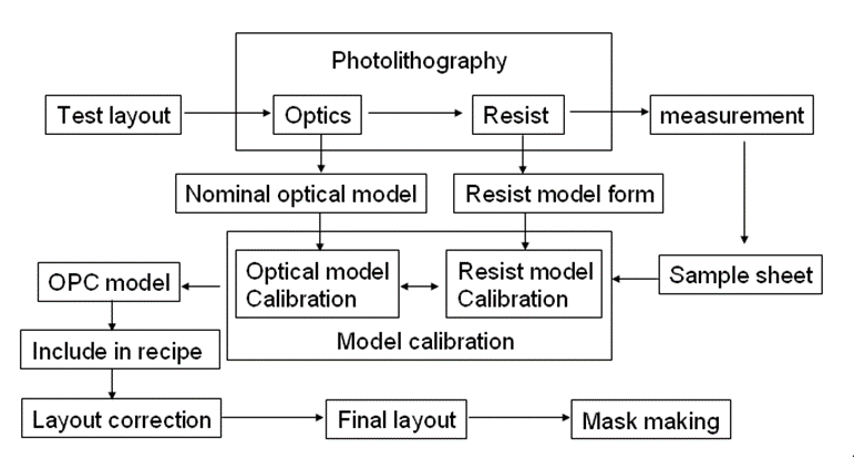
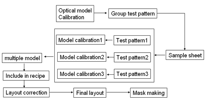
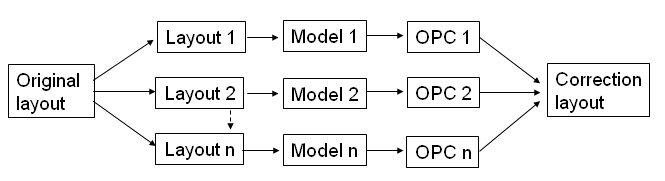
When models for different characteristics of test structures are constructed, they should be included in OPC recipe and used for simulation by OPC iterations. Different kinds of layout structures can be grouped by SVRF command and then corresponding model is implemented for each structure. This can be illustrated by Figure 6. The original layout is firstly checked by SVRF command which is designed as a basic language for layout geometry operation by Mentor Corporation, and then is selected into several groups that each has its own model. The OPC job then submitted with number of CPU processors and the fixed layout group will process by corresponding OPC model. All the groups of layouts will be combined together and output as a final gds file delivering to mask shop for mask making.


Figure 6.   Simulation and OPC correction based on multiple models.
5.   Conclusions
This paper introduces an innovative concept of multi-models in one layer OPC simulation. According to different characteristic features, multiple models are selected and applied respectively and the fitting on these features with poor resolution can be improved by re-optimizing. The various models can be used simultaneously in OPC flow by identifying different characteristic features respectively.
1.
R. E. Schlief, Effect of noise and data selection on goodness of OPC model fit, Proceedings of SPIE, Vol. 5754
2.
CORRELATION BETWEEN OPC MODEL ACCURACY AND IMAGE PARAMETERS
Article and author information
Qingchen Cao
Tianhui Li
Shuying Wang
Deyuan Xiao
Publication records
Published: Sept. 28, 2019 (Versions2
References
Journal of Microelectronic Manufacturing